
Introduction
The varied types of uninterruptible power supplies (UPS) and their attributes often cause confusion in the data center industry. For example, it is widely believed that there are only two types of UPS systems, namely standby UPS and on-line UPS. These two commonly used terms do not correctly describe many of the UPS systems available. Many misunderstandings about UPS systems are cleared up when the different types of UPS topologies are properly identified. UPS topology indicates the basic nature of the UPS design. Various vendors routinely produce models with similar designs, or topologies, but with very different performance characteristics.
Common design approaches are reviewed here, including brief explanations about how each topology works. This will help you to properly identify and compare systems.
UPS Types
A variety of design approaches are used to implement UPS systems, each with distinct performance characteristics. The most common design approaches are as follows:
• Standby
• Line interactive
• Standby-ferro
• Double conversion on-line
• Delta conversion on-line
1. The Standby UPS
The standby UPS is the most common type used for desktop computers. In the block diagram illustrated in Figure 1, the transfer switch is set to choose the filtered AC input as the primary power source (solid line path), and switches to the battery / inverter as the backup source should the primary source fail. When that happens, the transfer switch must operate to switch the load over to the battery / inverter backup power source (dashed path). The inverter only starts when the power fails, hence the name “standby.” High efficiency, small size, and low cost are the main benefits of this design. With proper filter and surge circuitry, these systems can also provide adequate noise filtration and surge suppression.
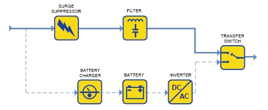
Figure 1 – The Standby UPS
2. The Line Interactive UPS
The line interactive UPS, illustrated in Figure 2, is the most common design used for small business, Web, and departmental servers. In this design, the battery-to-AC power converter (inverter) is always connected to the output of the UPS. Operating the inverter in reverse during times when the input AC power is normal provides battery charging.
When the input power fails, the transfer switch opens and the power flows from the battery to the UPS output. With the inverter always on and connected to the output, this design provides additional filtering and yields reduced switching transients when compared with the standby UPS topology.
In addition, the line interactive design usually incorporates a tap-changing transformer. This adds voltage regulation by adjusting transformer taps as the input voltage varies. Voltage regulation is an important feature when low voltage conditions exist, otherwise the UPS would transfer to battery and then eventually down the load. This more frequent battery usage can cause premature battery failure. However, the inverter can also be designed such that its failure will still permit power flow from the AC input to the output, which eliminates the potential of single point failure and effectively provides for two independent power paths. High efficiency, small size, low cost and high reliability coupled with the ability to correct low or high line voltage conditions make this the dominant type of UPS in the 0.5-5 kVA power range.
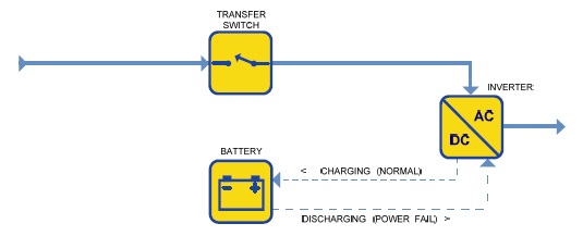
Figure 2 – The Line Interactive UPS
3. The Standby-Ferro UPS
The standby-ferro UPS was once the dominant form of UPS in the 3-15 kVA range. This design depends on a special saturating transformer that has three windings (power connections). The primary power path is from AC input, through a transfer switch, through the transformer, and to the output. In the case of a power failure, the transfer switch is opened, and the inverter picks up the output load.
In the standby-ferro design, the inverter is in the standby mode, and is energized when the input power fails and the transfer switch is opened. The transformer has a special “ferroresonant” capability, which provides limited voltage regulation and output waveform “shaping”. The isolation from AC power transients provided by the ferro transformer is as good as or better than any filter available. But the ferro transformer itself creates severe output voltage distortion and transients, which can be worse than a poor AC connection. Even though it is a standby UPS by design, the standby-ferro generates a great deal of heat because the ferro-resonant transformer is inherently inefficient. These transformers are also large relative to regular isolation transformers; so standby-ferro UPS are generally quite large and heavy.
Standby-ferro UPS systems are frequently represented as on-line units, even though they have a transfer switch, the inverter operates in the standby mode, and they exhibit a transfer characteristic during an AC power failure. Figure 3 illustrates this standby-ferro topology.

Figure 3 – The Standby Ferro UPS
High reliability and excellent line filtering are this design’s strengths. However, the design has very low efficiency combined with instability when used with some generators and newer power-factor corrected computers, causing the popularity of this design to decrease significantly.
The principal reason why standby-ferro UPS systems are no longer commonly used is that they can be fundamentally unstable when operating a modern computer power supply load. All large servers and routers use “power factor corrected” power supplies which draw only sinusoidal current from the utility, much like an incandescent bulb. This smooth current draw is achieved using capacitors, devices which ‘lead’ the applied voltage, ferro resonant UPS system utilize heavy core transformers which have an inductive characteristic, meaning that the current ‘lags’ the voltage. The combination of these two items form what is referred to as a ‘tank’ circuit. Resonance or ‘ringing’ in a tank circuit can cause high currents, which jeopardize the connected load.
4. The Double Conversion On-line UPS
This is the most common type of UPS above 10 kVA. The block diagram of the double conversion on-line UPS, illustrated in Figure 4, is the same as the standby, except that the primary power path is the inverter instead of the AC main.
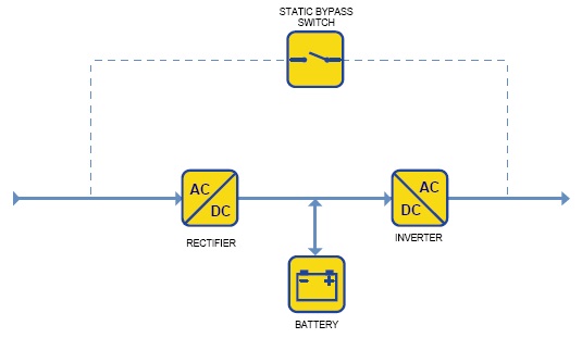
Figure 4 – The Double Conversion Online UPS
In the double conversion on-line design, failure of the input AC does not cause activation of the transfer switch, because the input AC is charging the backup battery source which provides power to the output inverter. Therefore, during an input AC power failure, on-line operation results in no transfer time. Both the battery charger and the inverter convert the entire load power flow in this design.
This UPS provides nearly ideal electrical output performance. But the constant wear on the power components reduces reliability over other designs. Also, the input power drawn by the large battery charger may be non-linear which can interfere with building power wiring or cause problems with standby generators.
5. The Delta Conversion On-line UPS
This UPS design, illustrated in Figure 5, is a newer, 10 year old technology introduced to eliminate the drawbacks of the double conversion on-line design and is available in sizes ranging from 5 kVA to 1.6 MW. Similar to the double conversion on-line design, the delta conversion on-line UPS always has the inverter supplying the load voltage. However, the additional delta converter also contributes power to the inverter output. Under conditions of AC failure or disturbances, this design exhibits behavior identical to the double conversion on-line.
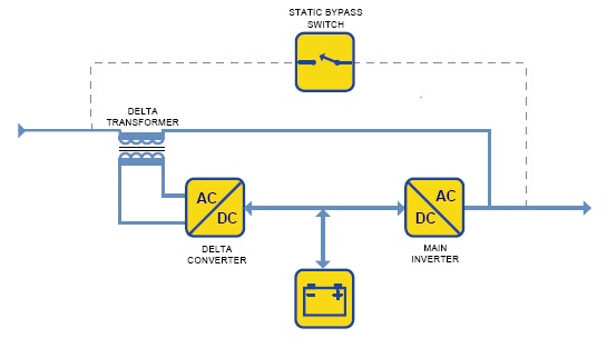
Figure 5 – The Delta Conversion Online UPS
A simple way to understand the energy efficiency of the delta conversion topology is to consider the energy required to deliver a package from the 4th floor to the 5th floor of a building as shown in Figure 6. Delta conversion technology saves energy by carrying the package only the difference (delta) between the starting and ending points. The double conversion on-line UPS converts the power to the battery and back again whereas the delta converter moves components of the power from input to the output.

Figure 6 – Analogy of Double Conversion vs. Delta Conversion
In the delta conversion on-line design, the delta converter acts with dual purposes. The first is to control the input power characteristics. This active front end draws power in a sinusoidal manner, minimizing harmonics reflected onto the utility. This ensures optimal utility and generator system compatibility, reducing heating and system wear in the power distribution system. The second function of the delta converter is to control input current in order to regulate charging of the battery system.
The delta conversion on-line UPS provides the same output characteristics as the double conversion on-line design. However, the input characteristics are often different. Delta conversion on-line designs provide dynamically-controlled, power factor corrected input, without the inefficient use of filter banks associated with traditional solutions. The most important benefit is a significant reduction in energy losses. The input power control also makes the UPS compatible with all generator sets and reduces the need for wiring and generator oversizing. Delta conversion on-line technology is the only core UPS technology today protected by patents and is therefore not likely to be available from a broad range of UPS suppliers.
During steady state conditions the delta converter allows the UPS to deliver power to the load with much greater efficiency than the double conversion design.
Summary of UPS Types
Table 1 shows some of the characteristics of the various UPS types. Some attributes of a UPS, like efficiency, are dictated by the choice of UPS type. Since implementation and manufactured quality more strongly impact characteristics such as reliability, these factors must be evaluated in addition to these design attributes.
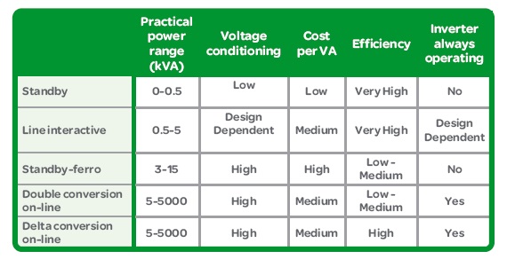
Table 1 – UPS Characteristics
Use of UPS Types in the Industry
The current UPS industry product offering has evolved over time to include many of these designs. The different UPS types have attributes that make them more or less suitable for different applications and the APC by Schneider Electric product line reflects this diversity as shown in Table 2. Energy efficiency has also play a large role in UPS designs. For example, most UPS systems do not include the internal transformers that were present in earlier designs. This evolution has increased efficiency while decreasing the weight, size, and raw materials consumption of UPS systems. Eco-mode is another example of energy efficiency but does come with some cost / benefit tradeoffs.
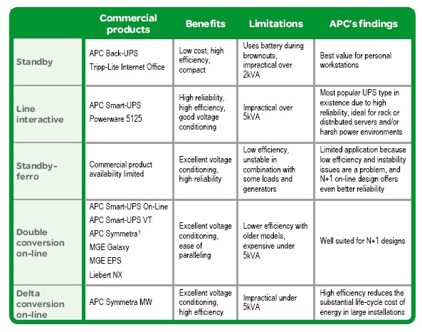
Table 2 – UPS Architecture Characteristics
Conclusion
Various UPS types are appropriate for different uses, and no single UPS type is ideal for all applications. The intent of this paper is to contrast the advantages and disadvantages of the various UPS topologies on the market today.
Significant differences in UPS designs offer theoretical and practical advantages for different purposes. Nevertheless, the basic quality of design implementation and manufactured quality are often dominant in determining the ultimate performance achieved in the customer application.